Braided Catheter Shaft Contract Manufacturing

Screen nominal wall space, then build a contract manufacturing RFQ. Use the report below to qualify tooling, process evidence and supplier terms. Engineering planning only; device performance and facility capability require review.

Prepared by Catheter Braiding OEM (CBOEM). First recorded: · Reviewed: .

Wall budget & RFQ builder

Enter OD, ID and length. See nominal jacket space instantly and copy a draft RFQ. Example defaults need engineering review.

1–30

0.008–0.36

10–260

Current liner: 0.0005 in; wire thickness: 0.0005 in. Edit these layers below. 1 mil = 0.001 in. Ranges are tool limits, not supplier capabilities.

Nominal geometry result

Positive nominal clearance — DFM review required

Total radial wall
3.28 mils
Braid envelope
1.00 mils
Remaining jacket
1.78 mils / 0.0452 mm

Liner: 0.50 mils · Braid: 1.00 mils · Jacket: 1.78 mils

Single concentric lumen, two undeformed wires at crossover; excludes tolerances, ovality, reflow and shrinkage. A positive result is not proof of manufacturability. Burst, torque, MR safety, sterilization, angle, coverage, machine time, price and delivery are unknown until reviewed.

Copy the brief, then paste it into your inquiry. No email has been sent.
Edit layers & contract scope

0.0003–0.0035

0.0003–0.004

0.0008–0.012

15–250

10–50000; whole units

Material, pattern, PPI, carrier count, phase and environment are recorded in the RFQ. They do not establish performance or certification.

Load an illustrative scenario

Examples are single-lumen arithmetic exercises. Pull wires, hubs and device performance are outside this model.

1. Four decisions before a manufacturing award

Treat the tool result as a drawing review prompt. The following are editorial procurement recommendations, grounded in the scope of the linked references; they do not certify a supplier.

Decision, evidence and next action
DecisionEvidence boundaryAction before award
Separate geometry from performanceNominal clearance cannot demonstrate device performance; S1 and S3 provide scope and reporting context.Agree tolerance stackup and device-specific bench acceptance criteria.
Qualify the quality systemQMSR incorporates ISO 13485:2016; applicability and supplier role still matter (S2).Check certificate scope/site, audit evidence and quality responsibilities.
Define contamination controlsAir particle classification is distinct from sterility and biological contamination (S4).Review process areas, monitoring and downstream cleaning/packaging scope.
Plan risk and change controlRisk management is device-specific (S10).Assign validation, change notification, transfer and requalification ownership.

Reference scope: [S1] [S2] [S3] [S4] [S10]

2. Reproduce the nominal wall calculation

The calculation assumes a concentric, single-lumen shaft and two undeformed wires at a crossover. French OD is a diameter scale: 1 Fr = 1/3 mm. It is not a circumference measurement. All dimensions below use inches after conversion.

Single-lumen radial wall accountingSingle-lumen radial wall accountingLumen ID: inner spaceLiner: one radial wallBraid: two-wire crossover envelopeJacket: remaining nominal radial spacePlanning schematic — not measured performance or a qualified process.
Schematic layer roles; not to scale. The result bar above uses your current inputs.
Nominal arithmetic and its limits
OutputFormulaLimit
ODOD_mm = Fr / 3; OD_in = OD_mm / 25.4Use finished OD, not usable lumen size.
Radial wall(OD_in − ID_in) / 2Excludes eccentricity and dimensional tolerances.
Crossover envelope2 × wire thickness or round-wire diameterNo ribbon rollover, compression or extra strands modeled.
Remaining jacketRadial wall − liner wall − crossover envelopePositive space is not proof of encapsulation or release readiness.
Thin-jacket triggerRemaining jacket < 0.0009 inIllustrative tool warning only; not a qualified minimum.

Changing PPI, pattern or material does not change this radial arithmetic. These choices are retained in the brief for supplier evaluation. Angle, coverage and line speed remain unknown without a defined braid/machine model.

3. Define the braid architecture before choosing equipment

A carrier count alone cannot establish torque, size range or productivity. Ask the supplier to return an explicit braid specification and a representative trial plan. Half-load also requires the actual loaded-carrier count; it is not interchangeable with a fully loaded braid.

Define the braid before comparing PPIDefine the braid before comparing PPIWire populationLoaded carriersStrands per carrierWire dimensionsArchitecturePattern and zonesPick-count conventionTension and setupTrial evidenceMeasured pitchCross sectionsFunctional test planPlanning schematic — not measured performance or a qualified process.
Architecture questions to resolve before interpreting pick count.
Architecture review checklist — editorial RFQ guidance
Input to resolveWhy it changes the reviewEvidence to request
Loaded carriers and strands per carrierChanges wire population and local stacking.Machine setup sheet and braid sample.
PPI definition and measurement locationDifferent pitch conventions cannot be compared directly.Count convention, gauge length and zoned pitch drawing.
Pattern and wire tensionChanges crossover arrangement and handling.Pattern image, tension window and dimensional observations.
Target mechanical behaviorCannot be inferred from count alone.Finished-shaft torque, bending and pressure test plan.

4. Compare wire profiles using the actual dimensions

At the dimensions in the example below, the arithmetic radial saving is 0.0016 in (1.6 mils). This comparison says nothing about equal coverage, equivalent strength or clinical suitability.

Example two-wire crossover envelopesExample two-wire crossover envelopesFlat: 2 × 0.0007 inEnvelope = 0.0014 inRound: 2 × 0.0015 inEnvelope = 0.0030 inPlanning schematic — not measured performance or a qualified process.
Two-wire crossover geometry; example thicknesses are dimensional inputs, not performance data.
Illustrative profile comparison
FactorFlat ribbon exampleRound wire exampleDecision check
Wire dimension0.0007 in thick × 0.003 in wide0.0015 in diameterConfirm actual material grade, condition and tolerance.
Two-wire envelope0.0014 in0.0030 inCompare radial space without assuming equivalent mechanics.
HandlingReview edge rollover and twistReview seating and tensionInspect cross sections after reflow.
Cost and availabilitySupplier quote requiredSupplier quote requiredCompare stocked sizes, MOQ, scrap and setup.
MR safetyUnknown for complete assemblyUnknown for complete assemblyAssess intended MR environment and labeling (S6).

[S6]

5. Review reflow settings and joint evidence

Specify the finished geometry and bond requirements first. Resin grade, moisture, shrink sleeve, stackup, equipment heat transfer and traverse motion determine the development window. No temperature, shrink pressure, speed or scarf length is prescribed here.

Reflow process development evidenceReflow process development evidenceIncoming stackLiner / braid / jacketSurface conditionSleeve and coreProcess studyThermal exposureMotion and coolingDocumented windowVerify assemblySections and surfaceLumen patencyBond / functional testsPlanning schematic — not measured performance or a qualified process.
Process controls to document during a representative reflow study.
Review each jacket transitionReview each jacket transitionDefine zonesActual resin gradesDrawing locationsJoint geometryChallenge processHeat-transfer changesFlow and overlapSleeve behaviorConfirm transitionLocal dimensionsBending behaviorTensile integrityPlanning schematic — not measured performance or a qualified process.
Zone transition review; no universal thermal recipe or joint length is implied.
Reflow failure modes and qualification actions
ObservationCandidate causes to investigateEvidence for the next decision
Exposed wire or voidsAvailable polymer, wire seating, thermal exposure and sleeve behaviorCross sections and surface inspection along the shaft.
Liner/jacket separationSurface condition, treatment age, material pair and thermal historyQualified bond test, aging and relevant functional tests.
Lumen restrictionCore support, polymer flow, shrink behavior and coolingID/patency check and local sections at transitions.
Transition kink or weak jointZone geometry, overlap and material pairingBending and tensile verification for the intended design.

ASTM D2578 is scoped to PE/PP film wetting tension; it is not evidence for a universal PTFE adhesion threshold. A screening method needs qualification and correlation to assembly performance [S5].

6. Qualify mandrel selection and removal

The core supports the lumen during processing. A stretch-removable core, a reusable rigid core and a release-coated core each require a material- and process-specific trial. Shaft size alone is insufficient to select a mandrel.

Compare core removal approachesCompare core removal approachesStretch coreRemoval clearanceSacrificial materialLiner damage studyRigid coreForce and frictionSurface finishReuse qualificationCoated coreRelease behaviorWear / residue checksCleaning qualificationPlanning schematic — not measured performance or a qualified process.
Removal strategies to evaluate; forces, elongation and reuse life are not established.
Tooling comparison — supplier review required
Core approachPotential tradeoffWhat to verify
Stretch-removable coreMay create removal clearance; adds sacrificial material and handlingTensile behavior, coating integrity, liner damage and cleanliness.
Rigid reusable coreMay spread tooling cost across runs; requires extraction and reuse controlsPull force trace, surface condition, dimensional reinspection and reuse limits.
Release-coated coreMay change interface friction; introduces coating controlsCoating wear, residue transfer and qualified cleaning.

Request documented trial results at the full working length. Do not assume a fixed extraction-force limit, Poisson neckdown value or number of reuse cycles.

7. Challenge the worst-case stackup

For a conservative jacket-space screen, use minimum finished OD, maximum ID, maximum liner thickness and maximum wire thickness. Remaining space = (OD_min − ID_max)/2 − liner_max − 2 × wire_max. This is a geometric bound, not a process capability study.

Worst-case radial clearance inputsWorst-case radial clearance inputsAvailable wallUse minimum ODUse maximum ID(OD min − ID max) / 2Layer demandMaximum liner wall2 × maximum wireLocal rollover reviewRemaining spaceSubtract layer demandAssess uncertaintyConfirm by trialPlanning schematic — not measured performance or a qualified process.
Worst-case input directions for a radial clearance review.

Illustrative sensitivity: a 0.0005 in decrease in OD removes 0.00025 in radial space. A 0.0001 in increase in liner wall removes another 0.0001 in. These values are arithmetic examples, not proposed manufacturing tolerances. The tool currently uses nominal values only.

Agree measurement resolution, uncertainty and sampling before interpreting capability. An external laser OD gauge does not directly establish lumen ID; qualify a suitable ID/patency method.

8. Match environmental controls to the process

The Class 7/8 selector records a requested environment; it does not establish a facility’s classification or a required room class for every catheter. ISO 14644-1 concerns airborne particles and does not characterize their biological nature [S4].

Environmental evidence to request
QuestionEvidence to inspectRemaining boundary
Which operations and rooms are covered?Classification report identifying rooms, operating state, dates and monitoringA room class alone does not cover every process or product.
How are contamination risks controlled?Process-specific cleaning, handling and environmental control planParticle class alone is not a bioburden or endotoxin result.
Who owns sterile release?Agreed packaging, sterilization and release responsibilitiesA shaft supplier may deliver nonsterile subassemblies.

9. Agree validation and release responsibilities

QMSR took effect February 2, 2026 and incorporates ISO 13485:2016 by reference [S2]. Review the supplier’s scope and your quality agreement. The roadmap below is editorial planning guidance; applicability, sample sizes and acceptance criteria must be justified for the process.

Agree quality evidence handoffsAgree quality evidence handoffsIncoming evidenceMaterial identityLot traceabilityAgreed inspectionProcess evidenceQualified equipmentApproved protocolsDeviations reviewedRelease evidenceInspection / test dataConformance reviewAuthorized releasePlanning schematic — not measured performance or a qualified process.
Evidence handoffs from incoming material through agreed lot release.
Validation planning checklist
StageQuestion to resolveReviewable output
IQIs the installed equipment/configuration documented and suitable?Approved installation and calibration evidence.
OQWhat process limits and failure modes need challenging?Justified process window and executed challenge results.
PQCan routine production meet the agreed requirements?Risk-based lots, samples and evidence against the approved protocol.
Lot releaseWho reviews conformance and authorizes shipment?Traceability, inspection/test records and release authorization.

This page establishes no universal three-lot rule, Cpk/Ppk target or Gage R&R acceptance limit. Include the rationale in the approved protocol.

Prepare a supplier evidence request

10. Define bench evidence instead of inferring performance

FDA’s bench guidance addresses report content [S3]. ISO 10555-1 has a sterile single-use intravascular catheter scope [S1]. Select applicable requirements from the actual device and intended use; the checklist below does not reproduce normative clauses or acceptance thresholds.

Torque response needs device test evidenceTorque response needs device test evidenceDefine setupPath and frictionRotation historyConditioning and loadRecord responseHub and tip angleLag and windupSudden release eventsAssess resultsApproved limitsFailure investigationDesign / process actionPlanning schematic — not measured performance or a qualified process.
Torque evidence checklist; no measured curve, guaranteed lag or clinical threshold is shown.
Editorial bench evidence checklist
PropertyProtocol detail to agreeDecision evidence
Tensile / joint integrityTest segment, conditioning, fixtures, pull rate and failure definitionMeasured distribution and failure location versus approved limits.
Pressure / leak / burstFluid, temperature, ramp or cycling, dwell and failure definitionObserved performance before and after relevant conditioning.
Bend / kink / patencyPath geometry, support, lumen load and collapse definitionPatency and recovery over representative use conditions.
Torque responsePath, friction, rotation history, hub/tip measurementLag, windup and sudden release observations against justified limits.
Particles and surface integritySimulated use, collection method and detection limitsDevice-specific risk assessment and justified acceptance criteria.

ASTM F2606 concerns stents/stent systems, not a general catheter kink test [S9]. MR marking is a separate topic [S6]. No braid count, wire profile or PPI alone establishes a burst rating or eliminates torque windup.

11. Validate the complete sterilization configuration

Confirm whether the contracted scope is a nonsterile shaft or a sterile finished device. EO process development/validation and EO/ECH residual evaluation are separate evidence questions [S7] [S8]. No method is approved for an assembly merely by selecting its liner and jacket.

Sterilization evidence depends on the assemblySterilization evidence depends on the assemblyEO routeValidated processEO / ECH residualsFunctional retentionRadiation routeActual grades / doseAging studyFunctional retentionMoist heat routeThermal / moisture riskGeometry retentionValidated configurationPlanning schematic — not measured performance or a qualified process.
Modality review questions; material compatibility and retained performance remain unverified.
Sterilization decision checklist — compatibility unknown
Route under considerationQuestions to resolveEvidence before release
Ethylene oxideCycle, packaging, absorption, aeration and residual limitsValidated cycle, residual evaluation and post-process functional evidence.
Gamma / electron beamActual resin grades, dose distribution and aging effectsMaterial supplier data plus finished-device testing at the qualified conditions.
Moist heatThermal/moisture exposure and geometry retentionCompatibility evidence and validated finished-device process.

As of 2026-10-25, ISO lists ISO 10993-7:2026 as published and the 2008 edition as withdrawn. Confirm market recognition and the edition in your protocol. Do not infer a fixed 48-hour aeration period, a universal residual dose, or complete property retention.

12. Use evidence gates for onboarding

Use the gates below to negotiate scope and spending. Timing and quantities remain quote-dependent; material availability, tooling changes and validation review can dominate the schedule.

Release spending against agreed evidence gatesRelease spending against agreed evidence gatesScope / prototypeDrawing and CTQsOpen risks and quoteFirst article reviewQualify processApproved protocolsExecuted evidenceDisposition of findingsRoutine supplyQuality agreementLot release recordsControlled changesPlanning schematic — not measured performance or a qualified process.
Progress after an agreed evidence gate, with milestones confirmed by the supplier.
Editorial onboarding plan
GateSponsor inputEvidence to approve before progressing
DFM and scopeDrawing revision, tolerances, application, CTQs and forecastsStackup review, open risks, assumptions and itemized quote.
Engineering buildApproved materials and prototype acceptance planFirst article evidence and observations; identify redesign needs.
Verification and validationFrozen design and approved protocols where applicableExecuted reports, deviations and agreed disposition.
Routine supplyQuality agreement, purchase orders and change controlsApproved release records, capacity and delivery commitment.

13. Compare quotes on equivalent scope

No public price, MOQ or delivery benchmark has been established for these examples. Request a quote that separates recurring unit cost, NRE and validation. A single nominal geometry cannot price a manufacturing program.

Quote normalization checklist
Cost / schedule driverAsk the supplierAction if unresolved
Material and tooling availabilityGrade, size, minimum buys, lead time and ownershipQuote alternatives with explicit requalification consequences.
Setup and yieldSetup allocation, expected scrap, inspection and accepted outputCompare cost per accepted shaft, with yield assumptions stated.
Validation and testingIncluded deliverables, destructive samples and approval dependenciesPrice development and validation as separate milestones.
Capacity and logisticsReserved capacity, shipment terms and milestone datesObtain a dated schedule and change-notification commitment.

14. Resolve misuse, cost and fit risks before award

This register is an editorial starting point, not a risk assessment of a particular device. Assign owners and verify mitigations within the sponsor’s risk process [S10].

Resolve sourcing risks with an owner and evidenceResolve sourcing risks with an owner and evidenceMisuse / fitUnmodeled featuresDevice-specific DFMSponsor engineeringBudget / deliverySetup and yieldQuote assumptionsProcurement ownerTransfer / changeIP and tool rightsRequalification planQuality / legal ownersPlanning schematic — not measured performance or a qualified process.
Open risk, evidence owner and mitigation handoff; no fabricated risk scores.
Procurement and engineering risk register
RiskConsequenceMinimum mitigation / alternative
Using nominal clearance as design approvalMissed tolerance or encapsulation failureRequire worst-case stackup and sample evidence; revise geometry when needed.
Applying the single-lumen model to a steerable shaftPull-wire channels or local structures consume unmodeled wallRequest a local assembly drawing and specialist DFM review.
Ignoring setup, scrap or test samplesBudget or quantity shortfallCompare quotes on accepted output and ask for an NRE/validation breakdown.
Assuming tooling or recipes transfer automaticallySupplier lock-in or transfer delayNegotiate ownership, background IP, access and transfer deliverables.
Substituting a resin without assessmentUnexpected processing, aging or test behaviorUse approved change control and justified requalification.

15. Four reproducible illustrative scenarios

These are arithmetic exercises using the first four tool presets, not customer cases, measured test results or approved devices. Load a preset above, subtract liner + twice the wire thickness from radial wall, and compare the result below. Names describe scale only; anatomical suitability is unverified.

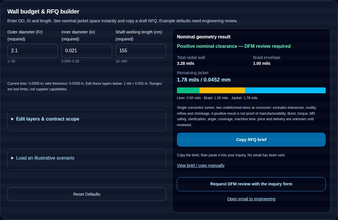
Contract manufacturing RFQ tool showing 2.1 Fr OD, 0.021 in ID and a calculated 1.78 mil nominal jacket budget
Actual tool execution captured 2026-10-25: 2.1 Fr OD, 0.021 in ID, 155 cm length, 0.0005 in liner and 0.0005 in wire thickness. Tool-only crop; site header and floating contact chrome hidden. Software evidence only, not a customer case, physical test or manufacturing capability claim.
Calculated nominal examples — no burst or torque data
ScenarioOD / ID inputsLayer inputsCalculated resultNext action
Micro-profile example2.1 Fr / 0.021 in ID0.0005 in liner; 0.0005 in wire thickness3.280 mils total; 1.780 mils jacketPositive nominal space: request DFM and test evidence.
Guide-shaft example6 Fr / 0.071 in ID0.0008 in liner; 0.0012 in wire thickness3.870 mils total; 0.670 mils jacketThin-jacket trigger: request tolerance review.
Larger single-lumen example8.5 Fr / 0.098 in ID0.001 in liner; 0.0008 in wire thickness6.774 mils total; 4.174 mils jacketPositive nominal space: request DFM and test evidence.
Large-bore example14 Fr / 0.165 in ID0.0015 in liner; 0.0012 in wire thickness9.364 mils total; 5.464 mils jacketPositive nominal space: request DFM and test evidence.

16. Normative Standards, References & Scope Boundaries

Source scope and links checked: 2026-10-25. Public catalog pages support scope summaries, not a full normative compliance review. The geometry model and procurement checklists are editorial aids. Full standards, device-specific evidence and applicable market requirements must be reviewed before approving a design or supplier. No private validation data or supplier capability evidence is supplied here.

[S1] ISO 10555-1:2023 — Intravascular catheters: general requirements

Open Official Standard Source (S1)

Applies to sterile, single-use intravascular catheters.

Boundary: The public catalog does not establish this tool’s jacket threshold, joint recipe or device-specific performance limits.

[S2] FDA — Quality Management System Regulation (QMSR)

Open Official Standard Source (S2)

Effective February 2, 2026; incorporates ISO 13485:2016 by reference into the amended 21 CFR Part 820.

Boundary: Applicability depends on the manufacturer’s role. This page and an RFQ do not establish compliance or facility certification.

[S3] FDA — Non-clinical bench performance reporting (2019)

Open Official Standard Source (S3)

Describes information for bench test protocols, summaries and complete reports in premarket submissions.

Boundary: It is reporting guidance, not a universal burst, torque, kink or sample-size specification.

[S4] ISO 14644-1:2015 — Air cleanliness classification

Open Official Standard Source (S4)

Classifies cleanroom air by particle concentration.

Boundary: Air classification alone does not establish sterility, bioburden, endotoxin control or suitability for this device.

[S5] ASTM D2578-23 — Wetting tension of PE and PP films

Open Official Standard Source (S5)

Its stated scope concerns polyethylene and polypropylene films.

Boundary: It is not a PTFE catheter bond qualification standard; no dyne threshold is adopted here.

[S6] FDA — MR safety testing and labeling (2023)

Open Official Standard Source (S6)

Addresses safety assessment and labeling of devices that may enter the MR environment.

Boundary: Selecting PEEK or Nitinol alone cannot establish finished-device MR safety.

[S7] ISO 11135:2014 — Ethylene oxide process validation

Open Official Standard Source (S7)

Addresses development, validation and routine control of EO sterilization processes.

Boundary: It does not validate a generic temperature or aeration duration for this shaft. Check edition and market requirements when agreeing a protocol.

[S8] ISO 10993-7:2026 — EO sterilization residuals

Open Official Standard Source (S8)

Published April 2026; addresses residual EO/ECH limits, measurement and conformity for device release.

Boundary: The 2008 edition is withdrawn. Confirm applicable editions and recognition with regulatory specialists; no single dose limit or fixed aeration time is inferred here.

[S9] ASTM F2606 — Three-point bending of stents and stent systems

Open Official Standard Source (S9)

Its stated scope is balloon-expandable vascular stents and stent systems.

Boundary: It is not used here as a general catheter kink-radius test or particulate acceptance standard.

[S10] ISO 14971:2019 — Medical device risk management

Open Official Standard Source (S10)

Describes a device lifecycle risk management process.

Boundary: Product-specific risk acceptability and verification plans require sponsor decisions; there is no universal acceptable risk score.
17. Engineering & Procurement Frequently Asked Questions

Tool & geometry

What does this contract manufacturing tool calculate?▼

It converts French OD to millimeters and inches, calculates nominal radial wall, subtracts liner thickness and a two-wire crossover envelope, and creates a preliminary RFQ brief. Other inputs record the requested scope.

Does a positive clearance establish manufacturability?▼

No. It omits tolerances, ovality, wire deformation, reflow, polymer flow and shrinkage. Use it to frame DFM questions, then qualify the actual construction.

Why is there a 0.0009 in jacket warning?▼

This is an illustrative editorial review trigger, not an ISO requirement or a supplier minimum. A value above it is not a qualified design; a value below it needs explicit tolerance and encapsulation review.

Why are angle, coverage and line speed not predicted?▼

PPI conventions, loaded carriers, strands per carrier, pattern and machine kinematics must be defined first. The tool records requested PPI and pattern without presenting an unverified geometric or throughput prediction.

Materials & process choices

How do I compare flat and round wire?▼

Compare crossover thickness at specified dimensions, ribbon handling, availability and finished-shaft test results. Neither profile alone guarantees torque, burst pressure or column strength.

Can a material choice prove MR safety?▼

No. Document the complete device configuration and intended MR conditions, and plan the safety assessment and labeling. Nonmetallic reinforcement alone is not a finished-device MR designation; see S6.

Do carrier counts correspond to fixed French-size ranges?▼

No range is established here. Ask the supplier to review diameter, loaded carriers, strands, pattern, pitch definition and equipment capability together, with a representative build.

Does the calculator account for pull wires or multiple lumens?▼

No. It models a single concentric lumen. Steerable assemblies, pull-wire channels, markers, tips and hubs need a separate local stackup and functional assessment.

Quality & evidence

Which cleanroom class is required?▼

Agree environmental controls from the process, contamination risk and finished-device requirements. Class 7 or 8 is an RFQ request, not proof of capability or sterility; ISO 14644-1 addresses airborne particle classification (S4).

What changed with FDA QMSR?▼

FDA states that the rule effective February 2, 2026 incorporates ISO 13485:2016 into the amended quality system regulation. Confirm the supplier’s role, applicable obligations and quality agreement (S2).

Are three lots and Cpk 1.33 always required for PQ?▼

This page adopts neither as a universal rule. The validation protocol must justify lots, samples, process challenges, measurement capability and acceptance criteria for the actual risk and process.

Can dyne pens release a PTFE liner bond?▼

No release criterion is established here. ASTM D2578 concerns PE/PP film wetting tension. Qualify any adapted screening method and correlate it with finished assembly bond evidence (S5).

RFQ & commercial terms

What should I send after copying the brief?▼

Paste the brief into the inquiry form or email, then provide drawing revision, tolerances, intended use, functional CTQs, quantities, annual forecast and delivery location. Agree a secure drawing exchange if needed.

Who owns tooling and process recipes?▼

Ownership is a negotiated contract term. Identify paid tooling, storage, maintenance, background IP, process know-how, transfer rights and return/disposal obligations before the award.

What price and delivery can this page promise?▼

None. Request an itemized quote covering NRE, materials, yield assumptions, setup, inspection, validation and delivery milestones. A nominal wall calculation cannot establish cost or schedule.

What if the result is invalid or copying fails?▼

Correct the highlighted inputs or reset defaults. A geometric conflict can be copied as a redesign request. If clipboard access fails, use the displayed text area to copy manually; the contact form and email remain available.

18. Submit Your Contract Manufacturing Specification & RFQ

Copy your specification brief from the tool, then send your drawing revision, tolerances and contract scope for engineering review. Agree a secure exchange for confidential drawings before sharing them.