Published · Reviewed · Public sources and explicit engineering assumptions; no measured production dataset supplied. Published by Catheter Braiding OEM. Send source corrections through the engineering contact form.
1. What to decide before committing to a pilot
Start with dimensional fit and a traceable process plan. A feasible nominal stack is the first screening step; a supplier still needs to establish its process and inspection evidence. The recommendations below are an engineering review framework, not measured supplier performance.
| Decision | What this page establishes | Evidence to request |
|---|---|---|
| Reserve radial space | Nominal jacket allowance from entered OD, ID, liner and wire; see method. | Worst-case tolerances and sectioned assemblies. |
| Confirm the line convention | Only measured picks/rev can unlock the conditional time estimate. | Machine counter definition and a measured setup coupon. |
| Review the complete thermal stack | Resin and sleeve information are separate inputs [S2, S3]. | Exact grades, equipment and assembled-part thermal trials. |
| Plan validation before scale-up | Cpk needs data; test documentation needs traceability [S4, S5]. | Approved protocols, measured lots, acceptance criteria and transfer records. |
For the first two rows the evidence is the reproducible arithmetic below. For material processing and validation, consult the primary references.[S2][S3][S4][S5]
2. How the planner works, and where it stops
All dimensions are nominal. French size converts as OD(mm) = Fr ÷ 3; 1 inch = 25.4 mm. The radial wall is half the OD–ID difference. The model assumes two uncompressed wires at a crossing; it does not model braid nesting or compaction.
| Output | Calculation | Boundary |
|---|---|---|
| Single radial wall (in) | (OD(Fr) ÷ 3 ÷ 25.4 − ID(in)) ÷ 2 | ID must be smaller than OD. |
| Crossing height (in) | 2 × wire thickness (flat) or diameter (round) | A nominal two-wire crossing, not a measured final braid layer. |
| Jacket allowance (in) | Radial wall − liner wall − crossing height | Zero or negative space blocks results and export. |
| Conditional line speed (cm/min) | Rotor RPM × confirmed picks/revolution ÷ PPI × 2.54 | The pick definition and rotor counter must match; otherwise withheld. |
| Ideal braid-only time (min) | Usable length (cm) ÷ conditional speed (cm/min) | No leads, setup, process losses or downstream operations. |
| Ideal batch braid hours | Braid-only minutes × whole batch units ÷ 60 | Not a promised production capacity or lead time. |
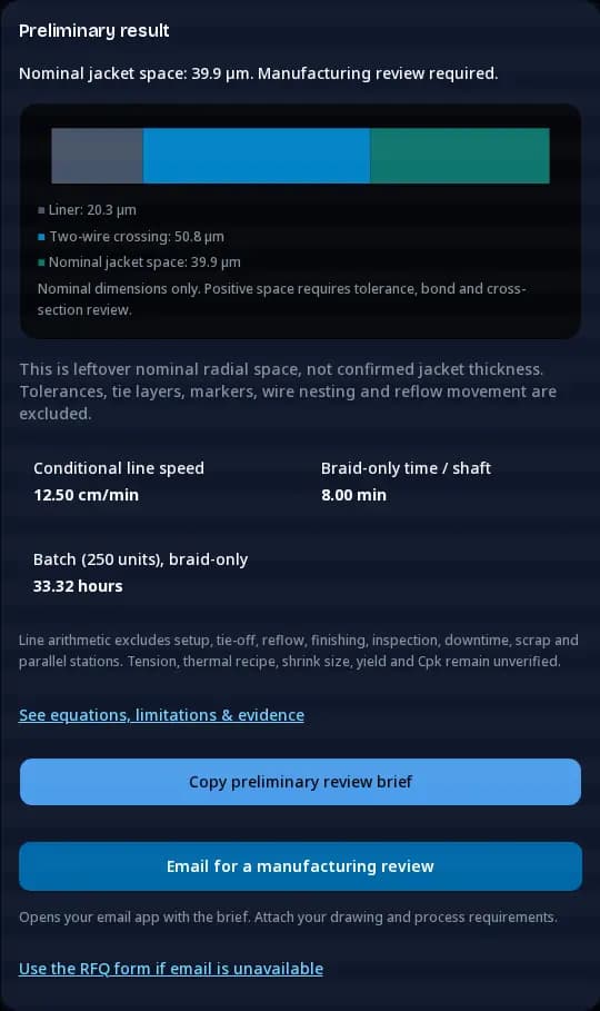
For example, if a machine-specific coupon confirms 8 counted picks per rotor revolution, 40 rotor RPM and 65 PPI give 12.50 cm/min. A 100 cm braid takes about 8.00 minutes before losses. This is an arithmetic example; 8 picks/revolution is not inferred from a 16-carrier label.
- 1. Confirm pick definition
- 2. Measure conversion
- 3. Estimate braid time
Wire width is recorded and checked against thickness, but no coverage, braid angle or stiffness is inferred here. The minimum and maximum input ranges are tool limits, not a supplier capability envelope. Defaults are hypothetical. An unknown line conversion can remain blank while the wall result stays usable.
3. Map the manufacturing route and its hold points
Use this route as a planning sequence. The supplier must adapt it to the actual liner, reinforcement, jacket, interfaces and equipment. Each hold point should produce a record that can travel with the lot.
- 1. Prepare liner & core
- 2. Braid, lay up & reflow
- 3. Extract, finish & inspect
| Operation | Review input | Hold point / record |
|---|---|---|
| Core and liner preparation | Drawing revision, core surface, liner ID and treatment identity | Incoming dimensions, traceability and preparation record. |
| Braiding | Wire section, carrier setup, pick convention and zone map | Coupon geometry, wire damage and equipment setup record. |
| Jacket layup | Exact resin grades, segment lengths, joints and sleeve fit | Assembly map and verified material identities. |
| Thermal processing | Part temperature, time, sleeve recovery and cooling | Trial record, dimensional change and bond/cross-section findings. |
| Extraction and finishing | Removal method, trims, interfaces and cleaning | Lumen inspection, surface damage and dimensional checks. |
| Release review | Approved requirements and relevant conditioning | Inspection disposition, test reports and deviations [S5]. |
Record both successful and failed trial conditions. A nominally acceptable OD does not reveal internal voids or liner damage; select complementary inspections in the protocol.
Define the build scope with the catheter braiding OEM capabilities and the shaft manufacturing process planner.
4. Choose the core and liner around removal evidence
The temporary core must support the assembly and be removable without damaging the lumen. A long, narrow lumen can make removal more demanding, but public evidence here does not justify a universal shaft-length cutoff, mandrel elongation target or scrap reduction.
| Choice | Review tradeoff | Minimum trial evidence |
|---|---|---|
| Sliding core | Surface condition, thermal changes and accumulated friction | Removal-force history and post-removal lumen condition. |
| Deformable / stretch-release core | Core deformation and debris / surface-damage control | Controlled removal method and dimensional inspection. |
| Liner surface treatment | Storage, treatment age and bond-system compatibility | Supplier handling requirements plus assembly-specific adhesion checks. |
| Alternative liner material | Wall, friction, thermal behavior and bonding approach | Material data and a complete-stack comparison against requirements. |
Do not adopt a dyne-pen pass limit solely because a source mentions ASTM D2578: its published subject is PE/PP films. Establish a suitable liner-specific assessment with the supplier.[S7]
- 1. Confirm core support
- 2. Trial removal method
- 3. Inspect the lumen
5. Control braid geometry before estimating speed
Document wire profile, material grade, carrier configuration and the target pick map along the shaft. Record what the machine calls a revolution and what the inspection method calls a pick. The planner deliberately uses a user-confirmed conversion rather than assuming every braider uses the same convention.
Under the planner’s two-wire model, a 0.0006 in flat wire contributes 0.0012 in at a crossing. That nominal height alone does not establish torque, hoop support or kink behavior. Wire width, lay, material state and composite bonding also need review.
For variable-pick shafts, obtain segment lengths and transition definitions. A single average PPI can hide a bottleneck. Estimate segment braid times separately using the same confirmed conversion, then add setup and handling from observed trials. Ask the supplier to inspect transition regions as well as steady sections.
- 1. Define zones & picks
- 2. Inspect setup coupon
- 3. Compare finished shaft
6. Build a thermal trial around the complete stack
Resin handling information and catheter assembly sleeve options are available from material suppliers. Neither source establishes a validated temperature or dwell for your shaft. Exact grades, additives and the assembly need to be identified first.[S2][S3]
| Input | Known from this planner | Confirm with supplier / trial |
|---|---|---|
| Jacket resin | Not selected or validated | Grade, additives, handling guidance and lot identity. |
| Heat-shrink sleeve | Not automatically sized | Expanded/recovered ID, wall, recovery conditions and removal. |
| Thermal history | No temperature or dwell recommendation | Equipment configuration, actual part history and cooling. |
| Multi-segment joints | Not evaluated | Segment geometry, bond behavior and mechanical transition checks. |
| Bond / surface outcome | Nominal radial allowance only | Cross-sections, adhesion evidence and appropriate functional tests. |
- 1. Identify grade & sleeve
- 2. Record part history
- 3. Inspect bonds & geometry
Use the observed failure mode to choose the next trial: apparent wire exposure, voids and joint changes may require different investigations. Changing heat and speed together without recording them makes attribution difficult.
Review catheter reflow and lamination requirements with the exact liner, wire and jacket grades.
7. Address misuse, cost and process-fit risks
This qualitative review list identifies questions to investigate. It assigns no fabricated failure frequencies or risk-priority scores. Update it with actual defects and the final device’s risk assessment.
| Risk | Possible decision error | Mitigation / alternative |
|---|---|---|
| Nominal fit mistaken for manufacturability | Reserve too little space after tolerances and extra layers | Review worst-case dimensions; section trial assemblies or revise OD/ID and wire. |
| Wrong pick convention | Quote an unrealistic braid speed | Confirm the machine/coupon conversion; omit speed until known. |
| Recipe copied from another grade | Treat resin data as an assembly process window | Identify exact materials and run recorded thermal trials [S2, S3]. |
| Prototype cost hidden in unit price | Ignore tooling, setup, inspection and destructive samples | Request separate non-recurring, trial and recurring cost lines. |
| Wrong reinforcement architecture | Optimize nominal profile before functional requirements | Compare braid, coil or hybrid builds using the same acceptance protocol. |
| Unverified production claim | Accept predicted yield or Cpk as release evidence | Request defined measured lots and statistical assessment [S4]. |
- 1. Record the uncertainty
- 2. Run the relevant trial
- 3. Revise plan or drawing
8. Compare architectures against the same requirement
Use these as candidate architectures, not performance rankings. The best choice depends on the complete composite, intended loads, interfaces and the evidence obtained from comparable samples.
| Candidate | Manufacturing questions | Comparison evidence |
|---|---|---|
| Braided reinforcement | Crossing wall, wire lay, pick zones and encapsulation | Torque response, bending / lumen patency and bond tests suited to intended use. |
| Coil reinforcement | Coil spacing, wall use, retention and jacket integration | Equivalent dimensional, mechanical and interface tests. |
| Braid + coil | Additional layer budget, assembly steps and process variation | Whole-stack sections and added-cost / performance justification. |
| Unreinforced shaft | Can a simpler stack meet the specified function? | Equivalent functional tests before accepting the simpler route. |
Define the decision test before comparing supplier samples. Keep sample dimensions, conditioning and test fixtures comparable, and record differences that prevent a direct comparison.[S5]
9. Separate pilot evidence from a scale-up promise
Cpk compares process variation with specification limits. A measurement system or a calculated wall stack cannot by itself guarantee a capability index. Use measured process data, an appropriate stability assessment and documented assumptions.[S4]
| Planning item | Tool treatment | Evidence for the quote |
|---|---|---|
| Steady braid time | Calculated only with confirmed conversion | Coupon measurement and observed run records. |
| Setup / handling | Excluded | Changeover, loading, tie-off and trial allocation. |
| Thermal processing / finishing | Excluded | Operation times, batch sizes and station arrangement. |
| Inspection / destructive tests | Excluded | Agreed methods, sampling and material consumption. |
| Scrap / rework / downtime | No assumed yield or OEE | Defined lot results and loss categories. |
| Delivery commitment | Not estimated | Material lead times, tooling, queue and agreed release documentation. |
- 1. Freeze requirements
- 2. Gather pilot records
- 3. Agree release & capacity
10. Three hypothetical planning examples
These are reproducible screening exercises, not customer case studies or measured production results. Each uses the planner’s starting dimensions and leaves the line conversion unknown.
1.7 Fr thin-wall example
OD 1.7 Fr; ID 0.017 in; liner 0.0005 in; flat wire 0.0006 in thick.
Nominal jacket space: 24.3 µm.
Process: subtract liner and a two-wire crossing from radial wall. Outcome: request tolerance and cross-section evidence; no validated fit or yield is claimed.
6 Fr guide-shaft example
OD 6 Fr; ID 0.07 in; liner 0.0008 in; flat wire 0.001 in thick.
Nominal jacket space: 39.9 µm.
Process: subtract liner and a two-wire crossing from radial wall. Outcome: request tolerance and cross-section evidence; no validated fit or yield is claimed.
8.5 Fr round-wire example
OD 8.5 Fr; ID 0.098 in; liner 0.0012 in; round wire 0.002 in thick.
Nominal jacket space: 40.0 µm.
Process: subtract liner and a two-wire crossing from radial wall. Outcome: request tolerance and cross-section evidence; no validated fit or yield is claimed.
Boundary exercise: change the first example’s ID from 0.017 to 0.021 in while leaving OD, liner and wire unchanged. The stack no longer leaves jacket space, so the planner blocks export. Revisit the dimensions instead of accepting a nominal zero jacket.
11. Scope the validation package before requesting a quote
ISO 10555-1:2023 covers general requirements for sterile single-use intravascular catheters; applicability to a shaft component and final-device responsibilities need review. The public abstract does not establish this project’s acceptance limits.[S1]
| Evidence area | Define in the protocol | Reference boundary |
|---|---|---|
| Dimensions and lumen | Drawing limits, locations, methods and measurement capability | The wall planner screens nominal dimensions only. |
| Bonds / interfaces | Applicable interfaces, conditioning, loads and failure definitions | Use traceable test methods and report deviations [S5]. |
| Leakage / pressure where relevant | Intended loads, fixture, conditioning and acceptance criteria | Review the applicable device standard and full text [S1]. |
| Bending / kink / torque where relevant | Sample geometry, lumen condition, fixtures and response criteria | ASTM F2606 is a stent / stent-system guide, not a universal shaft kink standard [S6]. |
| Capability / yield | Process stability, specification limits and lot definitions | Cpk and yield require measured data [S4]. |
| Sterilization / aging / cleanliness | Final-device conditions and the required shaft evidence | Not established by this calculation or bench-report guidance. |
Separate process controls from final-device verification. Assign owners for material traceability, equipment records, method suitability, conditioning and release disposition. Do not assume a universal Cpk target, sample count or number of lots from this page.
FDA’s December 2019 guidance concerns bench-test documentation. It does not replace separate work on sterilization, biological evaluation or other applicable topics.[S5]
12. Manufacturing questions by decision stage
Using the manufacturing planner
What can this braided catheter manufacturing tool decide?
It checks a nominal radial wall budget and, when a machine-confirmed picks-per-revolution conversion is supplied, calculates ideal braid-only time. Use the exported brief to request a drawing and pilot review. Positive space is not manufacturing approval.
Why is the line estimate initially withheld?
Picks per inch and the rotor or machine counter need a common counting convention. Carrier count alone does not establish the conversion used here. Leave measured picks per rotor revolution blank until the supplier or a setup coupon confirms it.
What happens when the liner and braid consume the wall?
The tool withholds results and export when liner thickness plus two wire thicknesses equals or exceeds the radial wall. Reduce the stack, reduce ID or increase OD, then review dimensional tolerances with the supplier.
Do preset dimensions represent tested catheter products?
No. They are hypothetical dimension sets for exploring the planner. They do not establish clinical suitability, supplier capability, burst performance or commercial yield.
Can I use braid-only hours as a delivery date or price?
No. Setup, layup, thermal processing, finishing, inspection, scrap, downtime and other orders are excluded. Request separate prototype, tooling, inspection and recurring-production quotes with explicit assumptions.
Materials and process choices
Should I choose flat or round reinforcement wire?
Compare thickness at the crossing, width, available wall and the intended mechanical tests. The tool uses twice the thickness or diameter as a nominal crossing height. It does not predict stiffness or torque. Confirm the result on a braided and reflowed cross-section.
How should a mandrel extraction method be selected?
Compare dimensional support, thermal compatibility, surface condition and extraction damage on the complete shaft. A stretch-release or sliding method needs a documented trial. This guide does not prescribe a universal elongation percentage or length cutoff.
How do I confirm PTFE liner surface preparation?
Request the supplier’s treatment identification, storage conditions and acceptance method, then verify bond performance on the actual construction. ASTM D2578 concerns PE/PP films; citing it does not establish a PTFE liner pass limit.
Can Shore hardness define the reflow temperature?
No. Obtain the exact resin grade and supplier processing data, then characterize the assembled stack on the intended equipment. Hardness alone does not capture grade, additives, sleeve recovery, dwell or temperature at the part.
How should I size a sacrificial heat-shrink sleeve?
Review its expanded ID, recovered ID and wall, recovery conditions, assembly clearance and removal method with the supplier. Check the full unprocessed stack. OD alone does not establish the required shrink ratio.
Pilot evidence and manufacturing transfer
Can the planner predict Cpk or first-pass yield?
No. Cpk needs specification limits and measured process variation with an appropriate statistical assessment. First-pass yield needs actual lot counts and a defined defect/rework policy. Neither can be inferred from the wall stack.
Which catheter tests should be specified?
Start with intended use, failure modes and the scope of applicable standards. Agree methods, conditioning, sample plans and acceptance criteria for dimensions, bonds, leakage, mechanical response and other relevant characteristics. This page does not assign universal pass limits.
Is ASTM F2606 a general catheter kink standard?
Its published scope is three-point bending of balloon-expandable vascular stents and stent systems. Review applicability before adapting a method, and define a shaft-specific kink or lumen-patency protocol where needed.
How should sterilization and aging enter a shaft review?
Identify the final device’s intended sterilization, packaging and shelf-life conditions. Agree which shaft characteristics need pre- and post-conditioning evidence. A dimension calculation does not establish compatibility with any sterilization cycle.
What should I send for an OEM manufacturing review?
Send a revision-controlled drawing, tolerances, material grades, reinforcement and jacket zone map, interfaces, intended functional requirements, prototype quantity, forecast and required documentation. Flag unknowns so the supplier can scope feasibility trials before quoting production.
13. Sources, scope and evidence limits
Public source pages checked on 2026-10-22. Standard editions are identified below; full requirements and market applicability need project-specific review. Supplier literature describes its own products. No private test data, certificate or commercial lot evidence was provided.
Manufacturing checklists, risk mitigations and hypothetical exercises are engineering inferences for review. They are not claims of validated performance. Public abstracts support scope statements, not undisclosed clauses or numerical acceptance limits.
- [S1] ISO 10555-1:2023 — General requirements
Supports: Public scope: sterile, single-use intravascular catheters.
Limit: Public abstract only; obtain the full applicable standard before selecting tests or limits.
- [S2] Arkema — Pebax processing guidelines
Supports: Resin processing and handling guidance.
Limit: Grade-specific resin information does not establish a finished shaft reflow recipe.
- [S3] Zeus — Catheter reflow and assembly aids
Supports: Heat-shrink sleeve options for catheter assembly.
Limit: Published sleeve choices are not a validated OD-to-shrink-ratio selection rule.
- [S4] NIST — What is process capability?
Supports: Capability compares measured process variation with specification limits.
Limit: Cpk requires process data and statistical assumptions; dimensions alone cannot predict it.
- [S5] FDA — Non-clinical bench performance test reporting, December 2019
Supports: Content of test protocols, summaries and reports for premarket submissions.
Limit: Reporting guidance; does not prescribe this shaft’s test limits or machine settings.
- [S6] ASTM F2606-08(2021) — Three-point bending of balloon-expandable vascular stents and stent systems
Supports: The publisher’s scope concerns stents and stent systems.
Limit: Do not describe it as a universal catheter kink test or apply it without a scope review.
- [S7] ASTM D2578-23 — Wetting tension of polyethylene and polypropylene films
Supports: The publisher identifies PE/PP films as the subject.
Limit: Does not establish a universal acceptance threshold for an etched PTFE catheter liner.
14. Turn the brief into an OEM manufacturing review
Send the planner brief with a revision-controlled drawing, tolerances, exact material grades, braid and jacket zone map, interfaces, functional requirements, prototype quantity and forecast. Mark unknowns so feasibility work can be scoped separately from a production quote.
For related work, explore braided catheter shaft contract manufacturing, braided catheter shaft CDMO services, braided catheter design or the reinforced shaft RFQ checklist.