Examples are editable inputs, not tested device recipes.
Range: 0.0003–0.005
Range: 0.001–0.01
Range: 0–0.005; 0 = linerless
Range: 1–250
Model: balanced 1-over-1 braid, one wire per carrier. PPI counts individual opposing-wire crossings along one wire per axial inch. Confirm this convention with your braider; group-pick and machine settings may differ. Ranges shown are tool limits, not manufacturing capabilities. Equations & limits
No validated performance prediction is available. Torque response, burst pressure, kink radius and adhesion remain unknown. Positive jacket space does not establish manufacturability.
Next: review dimensions, tolerances and a bench-test plan.
Opens your email app with the current results and limitations. Or use the RFQ form.
What the geometry screen can decide
Published . Technical content reviewed . This guide distinguishes calculated geometry, published supplier guidance and device-specific evidence still needed. No internal test dataset is claimed. Published by Catheter Braiding OEM; this is a geometry screening method, not an independently certified device assessment. Next scheduled review: April 2027, or earlier if the model, source scope or applicable requirements change.
Reserve radial space first
A liner, two-wire crossing and jacket must fit inside the single wall. Use tolerances before committing a drawing.[S1]
Compare complete architectures
Variable pitch, braid and coil are available construction options. Choose candidates against measured device requirements.[S2]
Validate the bonding process
Reflow must connect jacket and liner through the reinforcement. This process description does not supply a universal coverage or peel limit.[S4][S8]
Keep compliance separate from estimates
General catheter requirements and coating labeling guidance need device-specific application. A calculator result establishes neither.[S5][S9]
Known, estimated and unknown
Evidence class
Available here
Decision boundary
Known inputs
Entered dimensions, carrier count and crossing count.
Verify against a drawing and the braider’s counting convention.
Calculated estimates
Nominal wall, mean diameter, helix angle and projected coverage.
Idealized geometry; no wire crimp, compaction or tolerance propagation.
Unknown performance
Burst pressure, torque lag, kink radius, adhesion and yield.
Needs material data and representative physical testing.
Method, equations and reproducible assumptions
The geometric relationships below are the model definition, not a clinical performance correlation. It assumes a circular constant-diameter shaft, equal counter-rotating wire families, one wire per carrier, and 1-over-1 individual-wire crossings. All formula lengths use inches. French conversion is OD(mm) = Fr / 3; 1 in = 25.4 mm.
Concept schematic, not test data or a performance curve. Scroll the diagram on small screens.
Geometry model v2 — equations and limits
Output
Equation
Interpretation / limitation
Single wall W
W = (OD − ID) / 2
Reject ID ≥ OD. Each layer consumes radial space on one side.
Braid envelope B
B = 2t
Two uncompressed wires at a crossing; no assumed 15% compaction.
Jacket allowance J
J = W − l − 2t
J ≤ 0 flags an exhausted stack; J > 0 is nominal space only.
Mean braid diameter D
D = ID + 2l + 2t
Mid-surface of this simplified two-wire envelope; measure the actual formed braid.
Full-turn axial pitch L
L = C / PPI
One wire meets C opposing wires per full turn under the stated counting convention.
Angle α to shaft axis
α = atan(πD / L)
Right triangle from an unwrapped helix; reported in degrees.
Family fill F
F = Cw / (2πD cos α)
w is ribbon width or round-wire diameter, C is total carriers, l is liner thickness and t is wire thickness.
Projected coverage K
K = (2F − F²) × 100%
Ideal union of two strip families; only 0 ≤ F < 1. At F ≥ 1, withhold K.
Concept schematic, not test data or a performance curve. Scroll the diagram on small screens.
Coverage is projected surface occupancy, not measured optical coverage after forming. Round-wire projection, local overlaps, wire flattening and interlace crimp can change the result. The calculator does not map coverage to a reflow pass/fail threshold.
Reproduce the editable examples
Example
OD / ID
Angle
Projected coverage
Jacket allowance
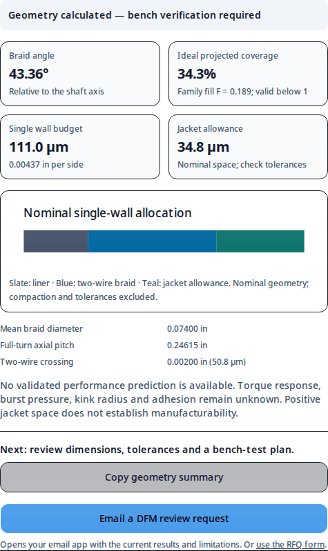
6 Fr guide example
6 Fr / 0.07 in
43.36°
34.3%
34.8 µm
2.1 Fr thin-wall example
2.1 Fr / 0.021 in
23.58°
50.6%
35.0 µm
8.5 Fr round-wire example
8.5 Fr / 0.098 in
27.04°
20.8%
45.1 µm
Other inputs for each row are listed in the worked scenarios. For tolerance analysis, use the minimum OD, maximum ID and maximum layer thicknesses together, then inspect actual sections. The nominal screen has no statistical capability model.
Software execution captured October 22, 2026 using case 1: 6 Fr OD, 0.070 in ID, 0.001 in liner, 0.001 × 0.004 in flat wire, 16 carriers and 65 PPI. The image shows only the calculator result panel; site navigation is outside the capture. This demonstrates reproducible software output, not physical testing or customer approval. The equations and numeric table remain available as text.
Architecture: fit every layer and transition
The liner, reinforcement and jacket share a radial budget; two wires overlap at a crossing.[S1] Markers, pull wires, tie layers and coatings need explicit drawing allowances beyond this tool.
Concept schematic, not test data or a performance curve. Scroll the diagram on small screens.Concept schematic, not test data or a performance curve. Scroll the diagram on small screens.
For a purely geometric comparison, two 0.002 in round wires reserve 0.004 in at a crossing; two 0.0007 in flat wires reserve 0.0014 in. The latter is 65% less crossing height in this example. Equal strength, coverage or torque is not implied.
Concept schematic, not test data or a performance curve. Scroll the diagram on small screens.
Document the proximal, transition and distal sections independently. Compare candidate overlaps and terminations in bend and tensile testing, rather than assuming a smooth pitch change eliminates kinks.
Select candidates against the actual failure mode
Supplier publications show variable-pitch, flat/round and braid/coil constructions.[S2] The table below is a proposed comparison plan. It is not a ranking of validated performance.
Architecture comparison plan
Candidate
What to compare
Constraint / alternative
Flat vs round wire
Crossing height, coverage, torque response and bending force at stated dimensions.
State whether dimensions, metal area or finished wall are held constant.
Constant vs variable pitch
Local flexibility and lumen retention along measured shaft zones.
A changed pitch also changes coverage; inspect transition regions.
Braid vs coil
Rotation response and lumen retention in the same fixture.
A coil is not an automatic substitute for a torque-transmitting braid.
Braid/coil hybrid
Composite profile and response at reinforcement overlaps.
If the wall budget is exhausted, consider separate zones instead of adding layers.
Material choices need grade-specific evidence
Medical PEBA grades span different hardness and flexural properties.[S3] Use supplier data for the exact resin, wire condition and processing history before interpreting a material substitution.
Material questions for the design review
Part
Record
Do not infer
Reinforcement
Alloy/fiber, temper, dimensions, coating, supplier and lot.
A nominal alloy name cannot establish finished-device torque or MRI labeling.
Liner
Material, thickness tolerance, surface treatment and storage conditions.
A treatment name cannot establish adhesion after the full heat history.
Jacket
Exact grade, hardness scale, additives, drying and sterilization compatibility.
A resin melting point is not a validated catheter reflow setpoint.
Markers and conductors
Position, local envelope, joining method and compatible processing.
The reinforcement-only wall estimate does not include these features.
No fixed Nitinol modulus, universal thermal limit, etch shelf life or material-only MRI claim is used in this guide. Request the relevant supplier qualification and device-specific evidence.
A fusing sleeve supports jacket reflow through the braid toward the liner.[S4] Develop the process on representative coupons, then verify it on the full assembly. The following is an engineering planning sequence.
Concept schematic, not test data or a performance curve. Scroll the diagram on small screens.
Process-development questions
Variable
Evidence to collect
Minimum next action
Liner surface
Supplier treatment specification and actual bond behavior.
Compare representative treated coupons after storage and thermal exposure.
Braid geometry
Crossing distribution, measured angle and local openings.
Inspect before and after reflow; investigate blocked openings or displaced wires.
Thermal process
Actual part temperature, dwell, sleeve recovery and cooling history.
Use controlled trial records rather than a generic temperature table.
Bond and surface
Defined peel/coupon geometry, microscopy and surface inspection.
Set justified criteria and investigate failure mode, not only force.
ASTM D1876 describes a T-peel configuration for flexible adherends. A slit catheter wall or different loading geometry needs a documented adaptation and rationale. A universal acceptance force is not established by citing the method.[S8]
Verification: connect each claim to a test
ISO 10555-1:2023 addresses general requirements for sterile, single-use intravascular catheters. Confirm applicability and exact clauses using the controlled full text; public catalog descriptions cannot establish test parameters.[S5]
Concept schematic, not test data or a performance curve. Scroll the diagram on small screens.
Proposed device verification plan — acceptance limits remain to be defined
Claim / concern
Record in the protocol
Evidence still needed
Tensile integrity
Shaft/joint locations, conditioning, loading method and failure mode.
Applicable standard clauses and justified device acceptance limits.
Leak / pressure performance
Intended use, assembly state, media, temperature and pressure history.
Validated device-specific leak/burst protocol; no calculator PSI rating.
Torque and rotation
Shaft length, fixture path, constraints and proximal/distal angle traces.
Lag, hysteresis and sudden release measured in representative configurations.
Kink / lumen retention
Bend method, radius definition, ovalization and use conditions.
Measured limits at the relevant shaft zones and junctions.
Bond durability
Coupon/assembly geometry and full manufacturing/conditioning history.
Justified bond criteria plus failure-mode inspection.
Coating performance
Location, compatibility, simulated use and labeling implications.
Device-specific evidence; FDA coating guidance concerns labeling considerations.
Scope correction: ASTM F2606 is for balloon-expandable stents and stent systems. ASTM F2528 is for enteral feeding devices with retention balloons. Neither is a general vascular-catheter torque or trackability acceptance standard.[S6][S7] FDA lubricious-coating guidance must also be read within its labeling scope.[S9]
Misuse, cost and application mismatch
Risks and practical alternatives
Risk
Impact
Mitigation / alternative
Treating geometry as performance
An untested pressure or torque claim can lead to an unsuitable device.
Use geometry to screen candidates and commission representative performance tests.
Nominal wall hides tolerance overlap
Reflow defects, rejected parts and repeated tooling work.
Review the worst-case drawing stack before prototype release.
Complex reinforcement adds cost
More transitions, setup and inspection can increase iteration effort.
Quote a simpler baseline and the proposed hybrid separately; compare measured benefit.
Fixture does not represent intended use
A candidate can pass an irrelevant bench comparison.
Define path, shaft length, constraints and device interactions before choosing the fixture.
Material or process substitution
A prior result may no longer represent the new assembly.
Document the change and determine which verification must be repeated.
Prices, yield and lead times are unknown without a program-specific quotation. For a geometry outside this model, the minimum useful next step is a controlled drawing review, not a guessed performance number.
Five worked scenarios: assumptions, calculation, next step
All cases are hypothetical model exercises, not clinical studies or tested production records. Use the stated inputs in the tool to reproduce each result.
Case 1: establish a nominal baseline
Inputs: 6 Fr OD, 0.070 in ID, 0.001 in liner, 0.001 × 0.004 in flat wire, 16 carriers, 65 PPI.
Next: If steering wires or marker bands are required, add their envelopes to the drawing before accepting the stack.
Case 4: reject unsupported coverage
Inputs: Use case 2, then set width to 0.010 in, carriers to 48 and PPI to 250. Other inputs stay unchanged.
Model result: Angle 20.95°; projected coverage outside model (F ≥ 1); jacket allowance 35.0 µm.
Next: Reduce projected packing or obtain measured geometry. Do not interpret an out-of-model fill factor as an optical coverage result.
Case 5: detect an exhausted wall budget
Inputs: Use case 1, increasing ID to 0.077 in. Other inputs stay unchanged.
Model result: Angle 45.95°; projected coverage 32.9%; jacket allowance -54.1 µm. No positive jacket space remains.
Next: Reduce ID or layer thickness, or increase OD. Request a drawing review before selecting an encapsulation process.
Prepare a reviewable OEM handoff
Concept schematic, not test data or a performance curve. Scroll the diagram on small screens.
Minimum review packet
Document
Include
If unknown
Drawing
OD/ID tolerances, usable length, zones, markers and joints.
Mark an open dimension and request feasibility feedback.
Construction recipe
Wire profile, carrier/wire count, pattern and pitch convention.
Ask for a candidate comparison instead of inventing a recipe.
Material list
Exact grades, treatments and processing constraints.
Identify the property or compatibility requirement to investigate.
Verification brief
Intended use, performance targets, fixture assumptions and quantity.
Agree requirements before interpreting a prototype as passing.
Use the tool’s geometry summary as an appendix. It carries the current assumptions and warnings; it does not replace the drawing or verification report.
Sources and evidence boundaries
Public sources checked on . Supplier guidance supports construction options; standards catalog pages establish scope only. Full standards and device-specific data remain necessary for conformity decisions. Equations, comparison plans and worked cases are explicitly identified as this page’s model or engineering proposals.
Labeling considerations for intravascular devices with lubricious coatings.
Labeling guidance, not a universal particulate-count protocol or proof that a coating is safe.
Frequently asked questions
Geometry & inputs
What does the braided catheter design calculator predict?
It calculates nominal wall space and simplified braid geometry. It does not predict a validated burst pressure, torque percentage, kink radius, clinical outcome or manufacturing yield.
What does PPI mean in this model?
PPI is the number of individual opposing-wire crossings encountered along one wire per axial inch. The model assumes a balanced 1-over-1 braid with one wire per carrier. Confirm the counting convention before entering a machine recipe.
Why are my dimensions rejected?
A field may be blank, non-finite or outside the displayed tool range; ID may equal or exceed OD; or a flat wire may be narrower than it is thick. Correct the marked field or reset the example. No previous numeric result is retained for invalid inputs.
Why can coverage be outside the model?
The projected-strip expression assumes each wire family occupies less than its available surface, F < 1. At F ≥ 1 it no longer describes separated wires in that family. The calculator withholds coverage instead of clamping an impossible result to a plausible percentage.
Materials & construction
Does flat wire always improve torque?
No. Thickness, width, alloy, interlace, jacket and shaft length all change the comparison. Evaluate profile and mechanical response together; an equal-thickness or equal-area comparison is different from an equal-width comparison.
Can I model a 2-over-2 or multi-wire braid?
Not directly. Group crossings and wire count differ from the tool assumptions. Obtain a measured full-turn pitch and a construction drawing, then use a model specific to that architecture.
What does a positive jacket allowance mean?
It means nominal radial space remains after subtracting the liner and two wire thicknesses. It excludes tolerances, wire nesting, tie layers, markers, coatings and reflow movement, so it is not an encapsulation or manufacturability approval.
Can I use a linerless construction?
Entering zero liner thickness models its geometric omission. Lumen surface quality, device compatibility, friction and process feasibility still need separate evaluation.
Evidence & verification
Is there a universally best braid angle?
No validated universal optimum is supplied here. Use the computed angle to describe geometry and compare candidates; select a design using measured response under the intended constraints.
Does ISO 10555-1 validate a braid recipe?
No. Its scope concerns the finished intravascular catheter. Applicability, clauses and verification criteria need a controlled assessment for the device; changing braid geometry does not establish conformity.
Are ASTM F2528 and F2606 catheter torque standards?
No. F2528 concerns enteral feeding devices with retention balloons. F2606 concerns three-point bending of balloon-expandable stents and stent systems. Neither establishes universal vascular-catheter torque acceptance limits.
Are the examples clinical studies?
No. All five scenarios are hypothetical model exercises with explicit inputs. They contain no patient data, production-lot test results or claims of clinical success.
Review & next steps
What should I send for a design review?
Send the geometry summary plus an OD/ID tolerance drawing, usable length, shaft zones, wire and polymer grades, joints, intended use, performance targets, quantity and timeline. Identify unknowns rather than filling them with assumed ratings.
What if copying the summary fails?
The tool displays a selectable text summary when clipboard access is denied or unavailable. The email link also includes current valid geometry and its limitations. For incomplete dimensions, it requests a drawing review without fabricated results.
Can non-metal reinforcement establish MRI compatibility?
No MRI labeling conclusion is made from a reinforcement selection. Assessment concerns the complete device and its intended conditions; markers, conductors, other components and appropriate testing must also be considered.
Where should I start when cost or timing is uncertain?
Request separate estimates for prototype setup, tooling, inspection and design iterations. Confirm material availability and the verification scope before agreeing a program schedule; this page supplies no universal price or lead time.
Turn the geometry screen into a testable design brief
Send your drawing, target use, material constraints and open questions for engineering review. Start from the tool’s current configuration or submit a brief through the RFQ form.